Monday, May 13, 2013

Final Blog Post

Project Description
Our project was to create a device that could open a window curtain by responding to exterior and interior light. The curtain would be on a stand meant to replace a real window frame. It would be a rod with shower curtain rings and a curtain hanging off. The curtain would start closed, open when there is an exterior light (the lamp), then close when there is interior darkness (covering the sensor). 


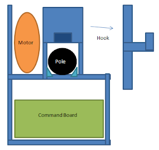
Our device is created to slide onto the rod and balance on it. There were four final compartments to the device. First was the box for the command board. Since this was the heaviest piece, the command board lay horizontally across the bottom. it had pegs that kept it from falling out of the bottom (attached by pegs and notches) and two piano-wired delrin pieces that could swing open and closed so that we could get the board in and out. Above this section were three vertical sections. In the image above, the left compartment was for the motor to sit in. All it had was two walls and a bottom. The motor wouldn't move around since it is attached to the machine through the axle that goes to the wheel. We used the nxt motor which was a little long but at an angle fit fine. The motor was connected to the command board through the side. The middle section is the wheel and rod compartment. The bottom 3cm of the compartment was left empty for the rod. There are four small right triangles in the corners of the walls and bottom to guide the rod so that it doesn't wobble. These side walls have holes centered in the remaining 5cm of the top. The wheels came from the lego set. They are 3cm wide with a 5cm diameter. There is a delrin piece that covers exactly where the the wheels go and have a hook attached to them. This hook holds on to the curtain loops that are right next to the vehicle. It helps it push the curtain and the prevents the rings from getting stuck in the wheels. The compartment to the right has two pieces of delrin connecting the walls. This is where we ended up putting our weight to balance the car. We used masses borrowed from the physics lab, totaling around 256 grams. There are two sensor attached to the command board- one that reads light and one that reads dark. These sensors were not attached to our machine but to the stand. 

Critical Elements

We had a few main points to research here
1) What type of window covering device?
We decided on a curtain and rod after looking at other sorts of devices on home depot and lowes. A curtain is found in most homes and in simple for humans to open and it was something we could easily recreate with out resources. 
2)Vehicle
We tested placement of the wheels- above, below, or one on each side of the rod- used this to guide our basic structure. We created a box-like design out of legos and revise this to get our current shape. We wanted a shape that was simple and would balance. Balance it turned out was our biggest challenge.
3)Sensors
We started off with the light sensors that were in the lego cabinet. The we found the small lego sensors which were much better and used them to get a light reading. Though this would ideally be reading sunlight and darkness in your room, for the exhibition we worked with the value of the lamp given.

Works-like model

For our works-like model we built a lego model. This kept falling apart so we knew that we wanted delrin to be our final material. Later we thought about using wood since we though it would be easier to attach but in the end delrin was out material. Our lego model has the same compartments as above except for the weight area. Also the hooks are not shown but they were part of out original design- they were just difficult to build out of lego. With the code we created on pico blocks, we were able to get the device to drive across the rod and return. Our kinks were that it was tilted and not balanced, and that it would go inconsistent distances. 


initial pico code using time instead of count

Looks-Like Model
We designed our model and pieces on Solid Works. We knew that this device was going to be a bit bulk so we tried to minimize our dimensions as much as we could. Also we could the peg and notch method for joining our pieces which is more aesthetically pleasing compared to heat staking which can get messy or to piano wire.  Our initial looks-like model looks just like our final model as described above except for the addition of the longer side wall for the weight. 

final delrin device

The other piece we had to build was out stand for the curtain device. This looked like two upside -down T 's connected by a Z. We displayed our final project out side Amy's office to get the full 'window' look.


Video

Photos


Final device with all its parts


over head shot
Final Code with count


in its natural habitat

The final product

Impressions and Improvements

I was surprised but how the project went. I was afraid that it was going to be stressful and difficult but it wasn't. Taking it step by step and seeing each step as improving upon our design rather than a failure made the process enjoyable. I learned a lot of new tricks such as how to properly measure for pegs and notches on solidworks and how to set a state on pico blocks (open?=1 or =0 and to have that be a condition). It was fun to test different iterations of the design and try to come up with ways to fix it. I am happy with our design and that it worked and how it worked but there are a few thing that  I would have liked to work on. 
I really enjoyed the exhibition and talking to people we new ideas about our project. Many people said that they really liked the idea and wished that they had one for their house. If I had more time and resources, I would have liked to get a command board that is much smaller. The board was the biggest piece and it threw off the balance. It also made the car big and minimizing the size would look better. I think with a smaller command board we could work with the balance around just the motor and the rod. I also had an idea that it would be cool to make a spherical vehicle- that way it is always right side up and never looks tilted. It would also make this aesthetically pleasing not make it an ugly appliance in your house. Another idea we had from talking to people was customization settings. We did think about this in out initial design but be had no idea how to make the settings changeable without pico blocks. Also an override button would be cool. Other people wanted their windows to be closed right as the sun went down rather that when they turn out the lights to prevent light pollution, some like the window closed at noon with the high sun and then open again in the evening. One person mentioned setting a time delay over the summer for the the sunrises at 5 in the morning and you want to sleep in, others liked the idea of a natural alarm clock. One person asked if they could get the pieces commercially so he could make his own. It was exciting to see people talking about our device in a real-world context. 


Final Project- More notes

Things we have changed since last time:
We printed off a new delrin side that rises higher. This creates a pocket to store masses in to balance the device. Finding the perfect balance was tough because sometimes it would be balanced when we put the masses in it but when it moved it tilted one way or another. Eventually we got it and it worked. 
We also put velcro on the rod to attach it to the stand so that it does not move around 
We also velcroed the motor onto the delrin base since it was bouncing a little bit when the motor was on. 
Final To-Do list with stand design and notes
Trials at the bottom

Another trial
After this, essentially all out trials consisted off adding and subtracting masses and rocks in the pocket to find the right balance

these are from earlier. They are just measurements of our delrin design


Saturday, May 11, 2013

Final Project: Final Steps and tests

After assembling our delrin box and all the pieces fitting together, we had a few things left on our to do list

1) Fixing the pico program
So when our car drives across the rod, it will go a longer distance forward than it goes backwards. This is because we had it on time. We changed our program to be based on distance with a count. This made the distances forward and back match better but they still don't match perfectly.

2)Wheels
When we built our initial vehicle with two wheels that are the same radius but they were different firmnesses- one was super squishy and the other was very tough. Since the distance forward and backward was still off, it was time to address the wheels. We found 2  firm wheels and tested them out (they slipped). We also switched the motor out and used squishy wheels. It drove across the rod very well with good speed and the distance it went was pretty consistent. 

3) Weight
To perfect our vehicle we had to get the balance right. I brought in a 'bag of nature' (rocks) to hang from the lighter side to get the balance. Over the weekend we used balloons filled with water. We found a nice, but not perfect balance with the rocks. It's good enough for now. This is something we can easily tweak later.

4) The Stand
Since this is meant to open a window curtain, we need a fake window frame for the exhibition. Here is what the design looked like:


Final Project: Delrin Part II

So some of our pieces didn't exactly fit together perfectly. I think that was because Hannah and I work on the pieces separately and even thought we gave each other the measurements, there was some sort of mis-communication about them. Hannah fixed the notches and pegs and revised some of the pieces. Instead of pegs in the horizontal walls between the motor and the wheels, it is connected to the horizontal base piece by a long notch- it essentially slides in from the side (and looks like a face). 

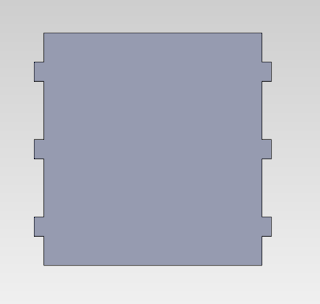
walls

Also, instead of a full back panel we switched to two little notches and pegs that will stick out and hold the board in. 
bottom piece 

the second horizontal piece- the base that the rod rests on and the top of the board box

The side walls of the base

the rest of the pieces


Final Appearance 

Final Project: delrin pieces

The next step in our project is creating the final pieces. Hannah created a solid works model of how we wanted our vehicle to look like while tried fixing the balance. We decided to use pegs and notches since that would be the simplest way of attaching the parts. Before we printed out all our part in notches, we needed to make sure we had the measurements right. After printing the test piece and getting the measurements right (the hole is .o1 cm smaller in length and width than the notch), we got to work. We decided to use the .495 cm delrin because it would be durable but not too thick that it would add weight. 


Above is our initial design. I drew this out because it was simple to create and put together, and we hoped to balance it out with weights later. Balancing with weights wasn't a good design idea so we manipulated the cardboard and lego models to find a structure with a good balance. We ended up moving one of our sides in more to save space and  so that it would be off-centered and balance on its own. We tested this out with the lego model and it worked.

We decided not to bend delrin since that would be difficult to connect and have all the pieces fit. There is a back behind the command board to hold it in. We also want to use a dovetail joint to attach the back piece  and pegs and notches on the other pieces. The horizontal pieces will have notches and the vertical pieces will have pegs at their ends. 

There is also the hook piece. This will cove the wheel- for aesthetics- and to hold the curtain rings. It will be a few mm above the pole as to not interfere with it. 


The pieces will be printed tomorrow. Hopefully they will fit and we will begin to move on to details- revising the code, building the stand, and fixing the balance. 


Friday, May 10, 2013

Final Project: works-like/ looks like model

 Here is our program: 

We have two sensors- one reading exterior light and one reading interior light. If the sensor reads normal light, it does nothing. If it reads light, the car drives 'this way' to open the curtain. If it reads darkness is drives 'that way' and closes the curtain. The time is set by motor on/off- we have found that 25 is the perfect time length of time. The only problem was that if the curtain was open, it would open again if it read sunlight again. Professor Berg showed us how to set open? so that if the curtain is open, it will not open again. The program knows only to open if the sensor read light AND if the curtain is currently closed. Writing the program was surprisingly straight forward. We will modify it later as we see fit. 

Next is our model
So we flipped the wheels back to over the rod and put the board under the rod. Our design right now has the wheels centered and the motor on the side. We are having problems with balancing the device so I'm sure our design is going to evolve. We have already went through a few iterations of trying to place the board on the top with the wheels under the rod. With that design, we tried to put the board in place where it would balance against the motor. With our current design I think what we want to do is move the board in the opposite direction of the motor a bit more so that we don't have to add artificial weight. Our final design will have a wall on the other side of the model and hooks for the curtain rings. We will also mess around with the exact location of the pieces with legos limit where we can put the walls. 

When we presented our model in class, it worked! The program ran smoothly and the lego model held together well. The only problem is balance. We are going to have to tweak this a lot. But it still moves even if the car is tipped over. 

Final Project: test 1-2 critical elements

We decided to go with opening a curtain with two wheels that drive along a curtain rod. 
Our critical elements were testing the light sensors and getting readings and then to build the frame of the vehicle. We used legos to build our initial frame. We built two walls and placed the wheels in between them. We started off with the pico motor and a gear train but then realized that the NXT motor would be much easier since we wouldn't have to adjust the speed or torque. 


We created a rounded (or stepped with the legos) base to hold the rod. The two wheels drive over the rod, the friction allowing them to grip and drive across the rod. The motor is only on one wheel, the other wheel does not have a motor attached to it but it allows the for better balance. This is just the basic skeleton, so when we build the works-like model we will have a better look. We created 'cradle' to hold the broom handle/ rod rather than a rectangular box. We thought that this would hold the rod better. Also we have the wheels over the rod since that we know for sure there will be contact between the wheels and the rod. The only problem is balance. The motor on the side makes the vehicle roll over. We have the device flipped over and the command board is on the top - we were afraid to go this at first since we thought that gravity would pull the wheels down and they wouldn't touch the rod. Before creating out final lego form, we thought about what our final delrin design would look like. It would be a delrin box with a divider between the motor and the wheels and another compartment for the board. We are going to try to curve delrin around the rod so it doesn't move around. 


The we tested the light sensors. It was cloudy so we got readings for cloudy light. We will test it again in the sun light. We also got sensor readings for ambient indoor light and the florescent lamp- these are the number we will likely use in our program.